Detector setup on Road editor
The detector is configured in the graphical user interface (GUI) as follows:
- Connecting to detector
- Turning on Tracking mode
- Setting up lanes
- Detector setup
- Setting up zones
- Turning on Tracing mode
Connecting to detector
The engineer's workstation software (ARM) includes the following basic components by default: adapter, detector, project
in order to simplify and speed up the initial setup of the detector.
Connecting to detector with road drawing
You should follow these steps to connect to a detector with road drawing:
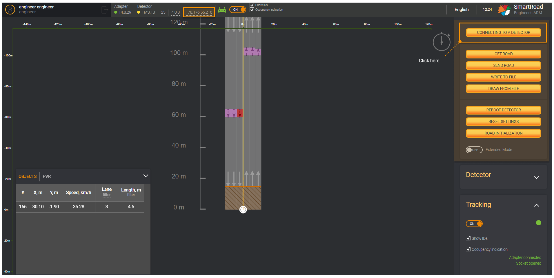
- Click on the
Connecting to detectorbutton in the side menu on the control panel or click on theIP addressin the information block.
- In the
Connecting to a detectorwindow that is displayed, you can enter the detectorIP addresswhich you want to connect, the port for data and the port for commands.
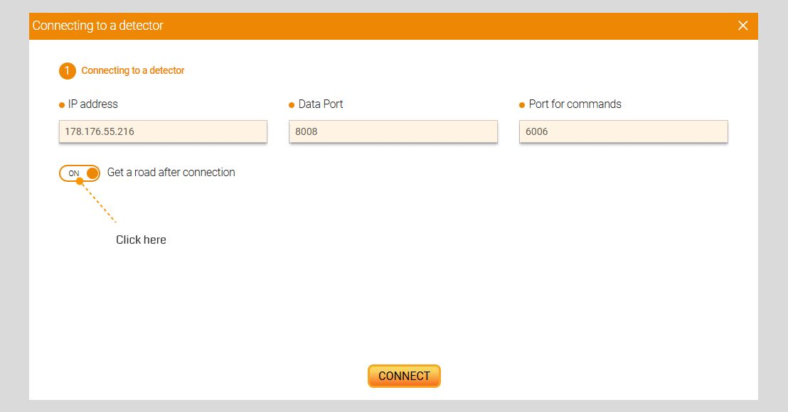
You may change the Detector IP address when requiring
- Check that
Get a road after connectionswitch button, it is turnedON. Then, click theConnectbutton.
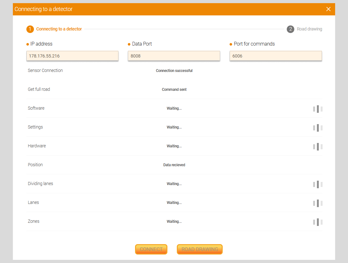
Подключение к детектору
| Field | Description |
|---|---|
| IP address | Detector IP address |
| Data Port | The value of the port from which the detector sends data. The default port value 8008 |
| Port for commands | The value of the port on which the detector receives control commands. The default port value is 6006 |
| Road drawing | Checking information for drawing the road and loading road data through the engineer’s workstation GUI |
- After sending all commands to the DT, press the button
Road Drawing
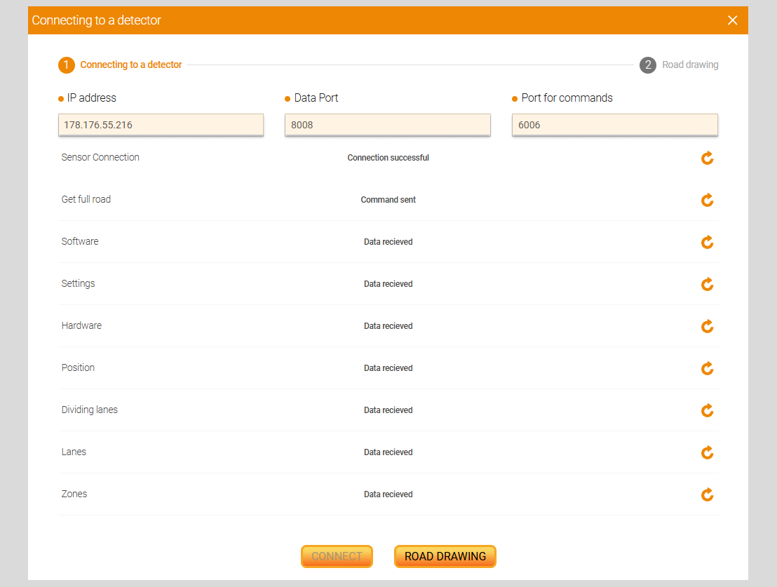
Next the proofreading message: The following information was obtained for drawing the road is shown ( i.e. drawing of the road with DT).
Besides, the data will be displayed in the form of a table.
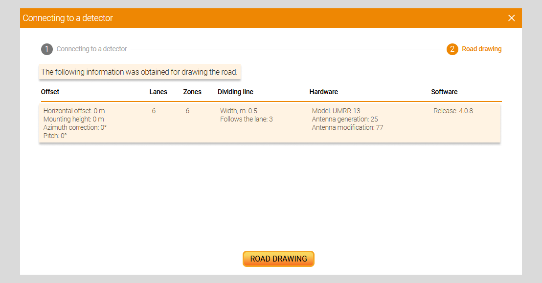
- Next, you should click on
Road Drawingbutton. A schematic representation of the DT, lanes and zones will appear in the road editor
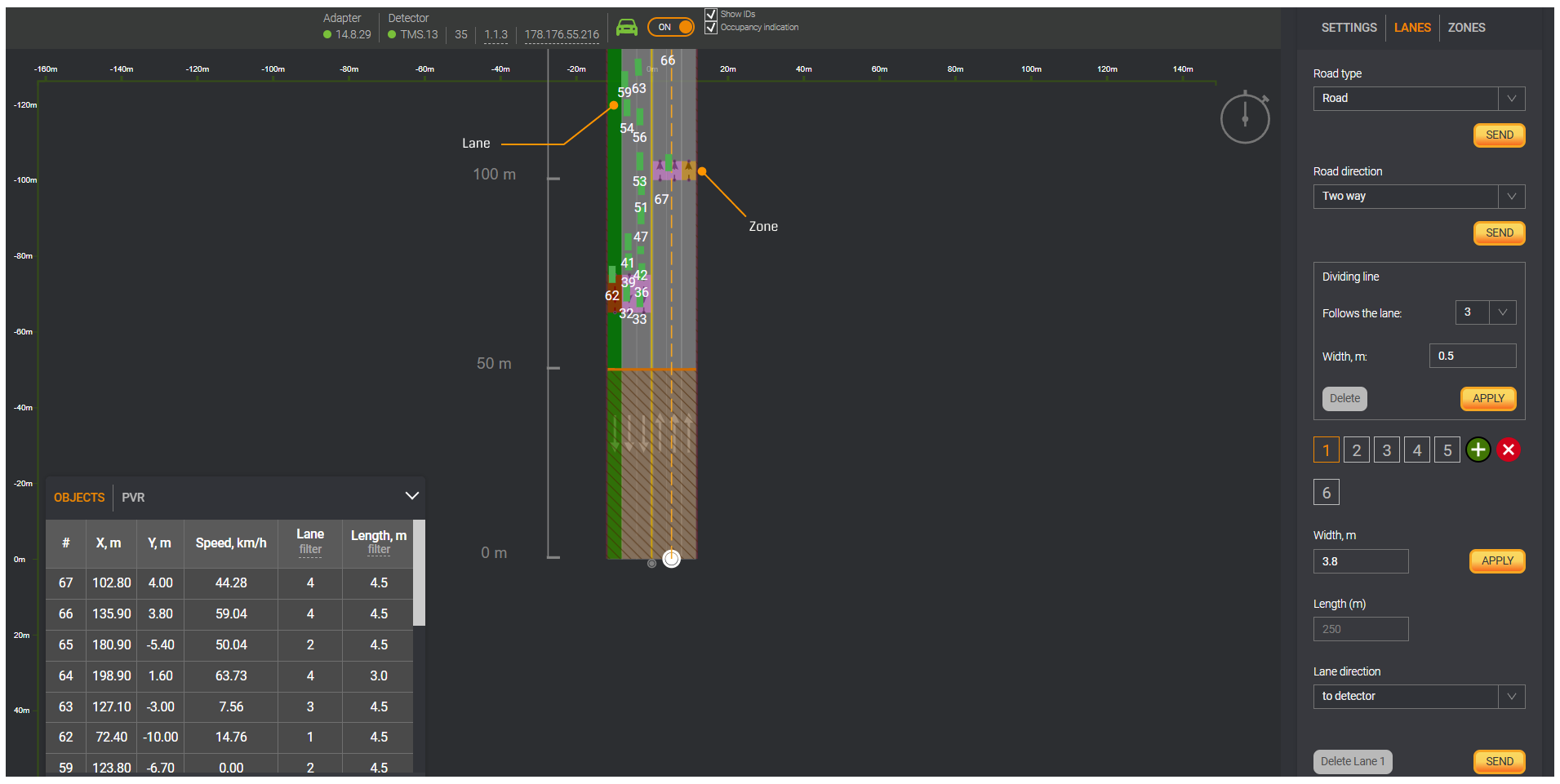
Connecting to detector without drawing a road
It may be used optionally when updating the firmware and changing the IP address to reduce the time for setting up the DT.
You should follow these steps to connect to a detector without road drawing:
Repeat the first 2 steps described in previous section.
Turn off
Get a road after connectiontoggle button. Then, click theConnectbutton.
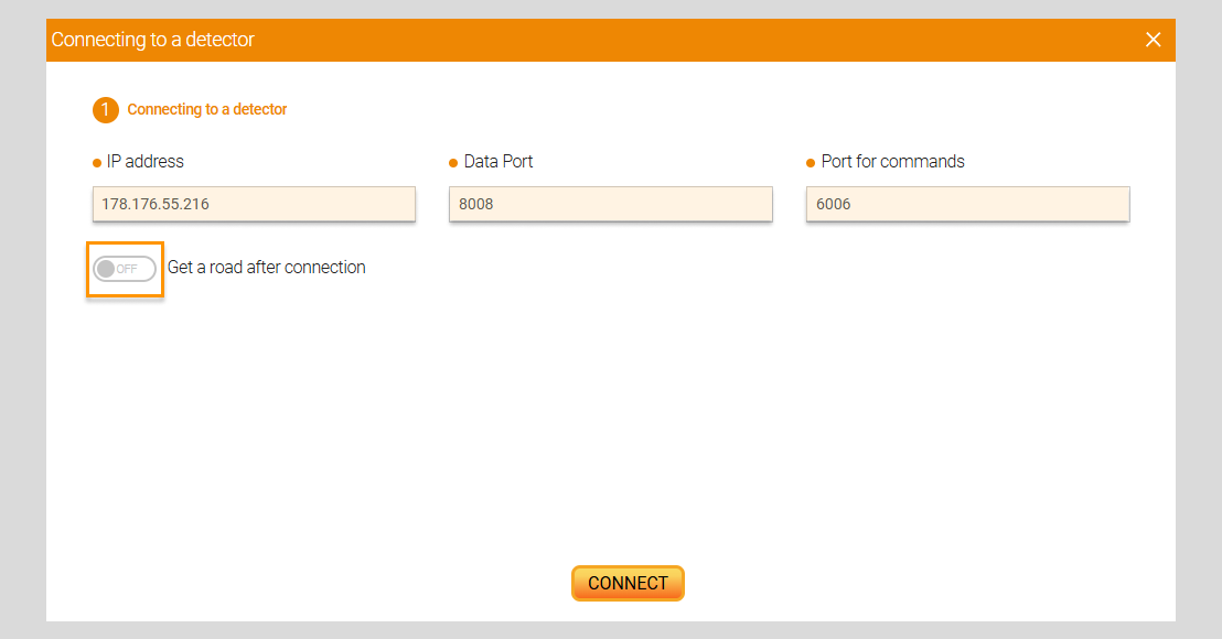
Connection to the detector
| Field | Description |
|---|---|
| IP address | Detector IP address |
| Data Port | The value of the port from which the detector sends data. The default port value is 8008 |
| Port for commands | The value of the port on which the detector receives control commands. Default port value 6006 |
Once all commands have been executed by DT, press the button Close. A schematic image of the DT will be displayed but without drawing
lanes and zones in the Road editor
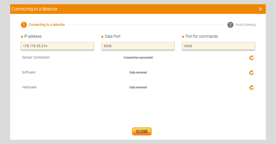
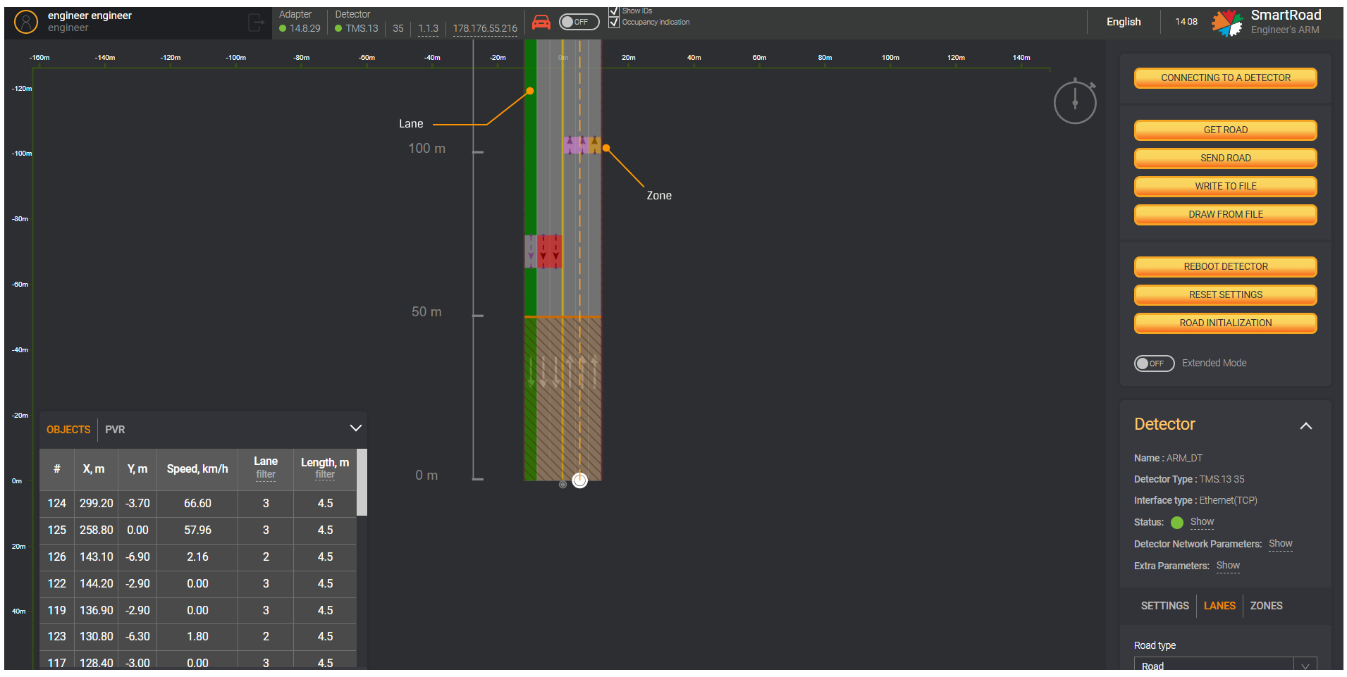
Errors when connecting to DT
If an attempt to connect to the DT fails, the message Connection error will appear. In that case, you must check in the fields
the entered values and click on the Update icon on the Connecting to detector window.
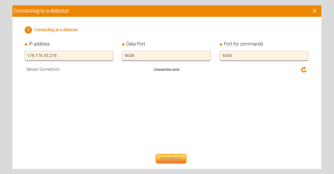
Tracking
The Tracking mode enables to display objects recorded by the detector in real time in Road editor. This mode allow to adjust
the settings of traffic lanes and detection zones in accordance with the movement of real traffic flow.
When turning on Tracking mode, the engineer can determine the accuracy of the road configuration and, if necessary,
additional detector adjustments can be completed.
This mode can be enabled in two ways.
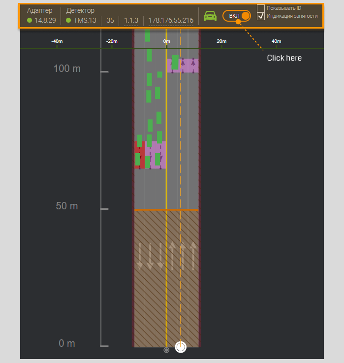
First Tracking method
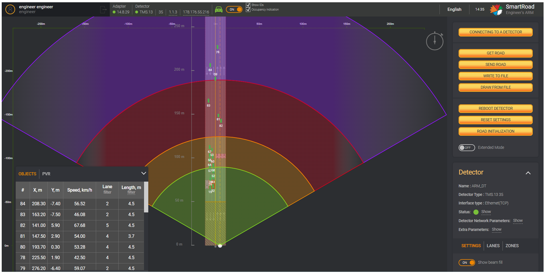
On the Information panel on the top, click on Tracking mode switch. Moving green rectangles will appear on the editor,
indicating the objects in the DT detection zone.
Second Tracking method
- In the side menu, expand the
Tracking block, if it is collapsed.
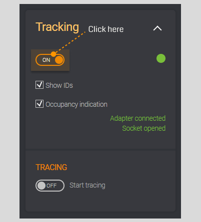
- Then, turn on the Tracking mode switch.
Moving green rectangles will appear in the road editor, indicating objects located in the detection zone of the DTs currently registered by the detector. In this case, the data monitoring block will display information about objects registered by the System.
If necessary, check the box next to Show object IDs. In this case, in addition to objects, the editor will show also
object ID numbers assigned by the System.
Setting up lanes
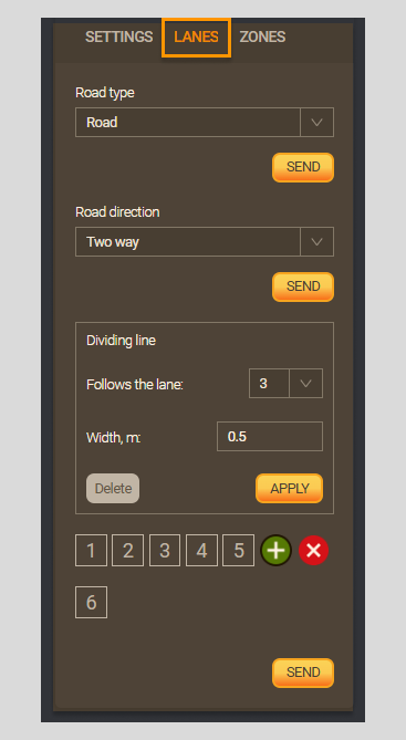
Lanes in the GUI simulate the location of lanes on a real road and allow you to link the data received from the detector to a specific lane.
Options for creating and editing lanes can de found in the Detector control block on the Lanes tab.
Tab Lanes
| Field | Description |
|---|---|
| Road type | In the drop-down list, select the road type that corresponds to the current road: - Road - Crossroads with EB - Crossroads without EB |
| Send (road type) | Sending the road type to the detector |
| Road direction | In the drop-down list, select the road direction: - One-way from the detector - One-way to the detector - Two-sided |
| Send (road direction ) | Sending the road direction to the detector |
| Follows the lane | In the drop-down list, select the lane number, followed by the dividing line. |
Width, m (Dividing line) | Width of the dividing line. Values can be from 0 to 5 m |
| Apply | Drawing a dividing line with parameters specified by the user |
| Delete | Removes the defined settings. After deleting custom options, the GUI will keep its default settings. |
Lane number (1,2,3,4,5) | Buttons for setting the number of lanes in accordance with the real road on which the detector is installed |
+ | Add a lane |
X | Delete the selected lane. If no lane is selected, the one of the right will be deleted. |
Width, m (configured lanes) | It indicates the width of the traffic lane. You can set from 0 м до 10 m |
| Apply | Drawing a lane with the specified width |
Length m | The value is set by the default depending on the detector type |
| Lane direction | In the drop-down list, select the lane direction: - From detector - Bidirectional - To detector |
| Delete Lane (indicate number) | Removing a lane |
| Send | Sending the configured band, all bands and all zones to the detector |
- Follows the lane - The parameters of the dividing lane will be transmitted to the detector
- Delete - the button appears when creating a dividing lane.
- Lane direction - When changing the direction of the lane (after clicking on
Applybutton), the direction of the zone is also modified
Steps to set up a lane
Open the
Lanestab in the Detector control block. If necessary, you may include additional lanes according to the actual road by clicking on+. The lane will be added to the right of the already created ones.Select a
Lane(select lane number) for setup.Set the
Road Directionto match the actual road.Enter the value in meters in the
Widthfield in accordance with the actual road. Click onApplyto the right of the value entry field to visualize the width change. This step must be repeated for each lane.When requiring, you can set also the
Dividing line:- This section for the
Dividing Lineis located at the top of theLanes Tap. - Select a lane from the
Follows the lanedrop-down list. - Enter a value in the
Widthfield in metersm. - Click on
Applybutton in this block to see the change in the workspace and save the changes in the System.
- This section for the
Click on
Sendbutton to save the lane settings in the System and send them to the detector.
Once setting is sent to the detector, the data is overwritten
If incorrect settings are sent, the detector's operation may turn nasty and the data received from the detector might be garbled
Detector setup
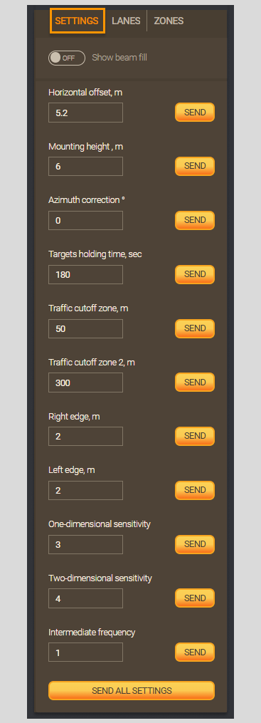
Setting an indentation from the edge of the roadway, it may be required for the correct operation of the detector, and also
increasing the accuracy of the received data. The mounting angles and heights can be found in the Settings tab in the
Detector control block.
Field description in Detector Settings Tab
| Field | Description |
|---|---|
| Show beam fill | The beam fill switch shows the detection efficiency at different distances from the detector by using segments of different colors |
Horizontal offset, m | The distance in meters from the center of the road (Dividing line) to the mounting point (installation location) of the detector. It can be can be indicated in a positive or negative direction. Values can be from 25 m to 25 m. |
| Mounting height , m | Height from the road surface to the detector mounting point. You can enter the following values from 0 m to 10 m. |
Azimuth correction ° | The angle of deviation of the detector from the center line of the road in a positive or negative direction. It allows you to adjust the direction of the detector beam by GUI. Possible values are from -12° to 12°. |
Targets holding time, sec | The time during which the detector detects an object on detection zone. It can be configured at an adaptive intersection. Values are from 0 to 180 sec |
Traffic cutoff zone, m | The distance of the blind zone from the detector - Values from 0 m to 60 m. |
Traffic cutoff zone 2, m | It works similar to traffic cut-off zone, m but on the opposite side of the road. This zone starts from the end of the road to the point that the user specifies in the field. Values from 50 to 450 m. |
Right edge, m | Used to add the edge of the road on the right side. The distance in meters over which the detector will see objects and attract them to the outermost lane. It is used on T-35 detectors. This value can be greater than or equal to 1, as well as 0. In case of absence (0), it will not be graphically displayed and vehicles will not be fixed. Values from 0 to 50 m. |
Left edge, m | Used to add the edge of the road on the left side. The distance in meters over which the detector will see objects and attract them to the outermost lane. It is used on T-35 detectors. This value can be greater than or equal to 1, as well as 0. In case of absence (0), it will not be graphically displayed and vehicles will not be fixed. Values from 0 to 50 m. |
| One-dimensional sensitivity | The characteristic is displayed only for detectors, which has two antennas (DT variants TMS.13 Т-25 and Т-35), it allows you to adjust the sensitivity of one antenna relative to the other. The default value 4. One-dimensional and two-dimensional sensitivity parameters are used for setup. Field values are from 0 to 20. Range of change for both also 0 to 20 |
| Two-dimensional sensitivity | It is used only on T-35 - Values are from 0 to 20 |
| Intermediate frequency (IF) | Frequency offset of the detector during signal transmission or reception. The signal is shifted to the IF to eliminate interference from other equipment that may work also in the same frequency - Values from 0 to 9 |
| Send all settings | Sending the specified configuration, all bands, and all zones to the detector |
If the DT T-35 incorrectly measures vehicle lengths, you can achieve the necessary accuracy of measuring vehicle lengths by changing the two-dimensional and one-dimensional sensitivity of the DT.
Steps to set up detector:
In the
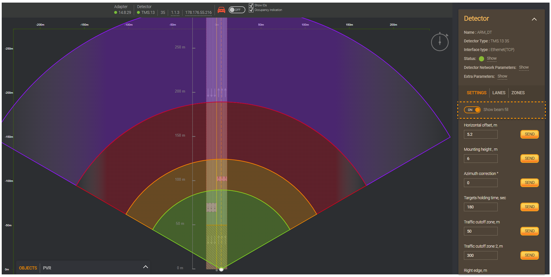
Detector control block, go to theSettingstab.When requiring, you can set the switch on
Show beam fill. Filling the ray with segments of different colors shows detection efficiency at different distances from the detector.
In the
Horizontal offsetfield, the distance in meters from the middle of the road to the installation/placement point (installation location) of the detector is indicated. It can be indicated in a positive or negative direction (a positive value is offset to the right, a negative value is offset to the left).The
Mounting heightfield indicates the height from the road surface to the detector mounting point.The
Azimuth correctionfield indicates the angle of deviation of the detector from the centerline of the road in a positive or negative direction. In this way is possible to adjust the direction of the detector ray in the Road editor.Send the configuration to the detector using the button
Sendfor each item separately. If you want to send all items at once, then use the buttonSend all Settingson the detector block in the control panel.
Once setting is sent to the detector, the data is overwritten
If incorrect settings are sent, the detector's operation may turn nasty and the data received from the detector might be garbled
Setting up zones
You can click on the required zone or go to the Zones tab in the Detector control block to configure detection zones.
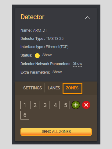
Field in Tab Zones
| Field | Description |
|---|---|
Zone number (1,2,3,4) | Buttons for setting detection zones, the number corresponds to those displayed on the road editor GUI. The number of zones at a non-adaptive intersection should correspond to the number of lanes on a straight road. When setting up an adaptive intersection, the number of zones may differ from the number of lanes |
+ for adding zone | Click to add the selected zone |
X for deleting zone | Click to delete the selected zone. If no zone is selected, the zone with the highest number will be deleted |
| Link to lane | In the drop-down list, select the number of the lane to which selected zone will be assigned |
Distance from the detector , m | The field indicates the distance from the detector installation location to the detection zone. The distance range from the zone detector depends on the type of detector. In case of DT T-25 from 0 m to 200 m, and for DT T-35 from 0 to 300 m |
Length, m | The field indicates the length of the zone where objects are registered. Values are from 1 m to 150 м |
| Zone direction | In this drop-down list, select the direction of the detection zone. The zone direction must correspond to the lane direction : - Bidirectional - To detector - Presence to detector - Presence from detector - From detector |
| Send all zones | Sending all zones and all bands to the detector |
- Zone numbers (
1,2,3,4) - The zone number indicated, it must correspond to the number of lanes on a straight road, and may differ from the number of lanes when setting up an adaptive intersection. - Distance from the detector - The range of distance from the zone detector depends on the type of detector.
DT T-25from0 m to 200 m,DT T-35from0 to 300 m. - Zone direction - If the zone is occupied (i.e., for busy zones), the value
1is passed, if the zone is free,0is passed.
Steps to configure zones
- In the
Detector control block, open theZonestab. If necessary, removeXor add+zones according to the actual road.
The zone will not be displayed in the GUI until the Save button is pressed.
Select zone number (
1,2,3,4) to add it on the road editor and configure it.In the
Link to lanedrop-down list, select a lane number to bind the selected zone to a specific lane.In the
Distance from the detectorfield, specify the distance to the start detection zones in meters.In the
Lengthfield, specify the length of the detection zone for the configurable lane.In the
Zone directiondrop-down list, select the direction of the detection zone.Click on
Addto include a zone and display it on the road, or you can undo the changes by clicking onCancel.Click on
Send all zonesTo save the zone settings in the System and send the settings to the detector.
Once setting is sent to the detector, the data is overwritten
If incorrect settings are sent, the detector's operation may turn nasty and the data received from the detector might be garbled
Tracing
First of all, Tracing control block will appear in the sidebar only after turning on the Tracking mode. Besides, you
must turn on Run tracing switch to display in the GUI the trajectories of objects moving over time
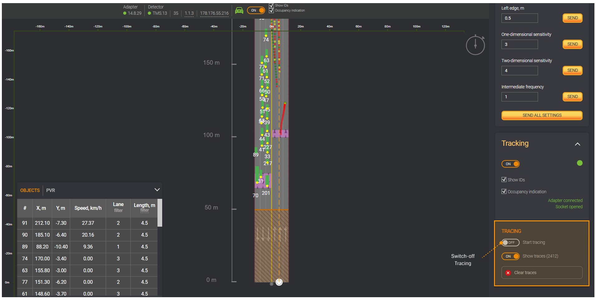
In parentheses next to the Show traces switch, the number of traces received since the trace was started is displayed.
If the recorded tracks overlap and interfere with the perception of information, you can delete them with the Clear traces button.
Finally, switch the Stop tracing to OFF to end the Tracing mode. Furthermore, Tracing stops automatically when
turning on Show traces.
Changing the detector's IP address
This functionality is used when connecting to the detector for the first time or when changing the addressing plan,
i.e. when it is necessary to change the default IP address in the detector to the connection IP address in accordance
with the addressing plan issued by the customer (standard IP address for PUIDD 192.168.10.10, for the new series
detectors 203.0.113.64).
You should follow these steps for changing the Detector IP address:
- Go to the Detector control block in the section
Detector network parameters. Then, click onShowbutton. - Enter new data in the fields: Detector
IP address(i.e. the IP address of the router or SIM card), thesubnet maskof the detector, thegatewayof the detector. Next, click onSendbutton. - Fields where the values are entered incorrectly will be highlighted in
red, and the values in them must be changed.