Detectors
The Detectors section is designed to add, edit, configure, and remove detectors from the System.
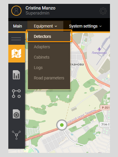
When you click on Menu item Detectors, you go to the detectors page which contains a filter and a list of all detectors existing
in the System.
The filter sets parameters for selecting detectors by name, project, connection status, detector ID, index, and primary data analysis.
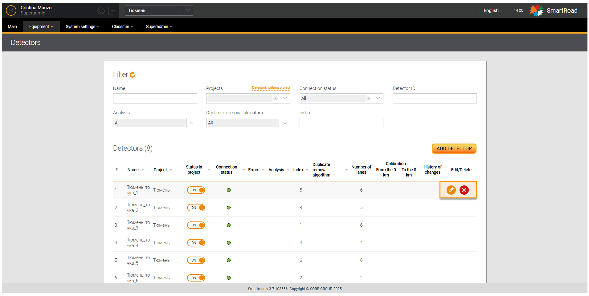
Next to the list name of Detectors, information about the total number of detectors in the System is displayed.
In the table below the Filter parameters on the Detector page
| Parameter | Description |
|---|---|
| Name | Field for entering the detector name |
| Projects | The drop-down list displays a list of projects available to the user |
| Detectors without project | Clicking on the button displays all detectors that are not associated with the project |
| Connection status | The drop-down list displays a list of available detector operating statuses. The choice is made by setting a checkbox. By default, all connection statuses are selected |
| Detector ID | Field for quick sorting of detectors by detector ID |
| Analysis | Application of primary analysis of data coming from the detector |
| Index | The detector index is entered in the field, which is assigned depending on the number of detectors in this project |
The list allows you to sort by the parameters specified. In addition, the Detector list parameters
| Parameter | Description |
|---|---|
| # | The serial number of the entry in the list |
| Name | Detector name specified when adding the detector to the system |
| Project | The project to which the detector belongs in the System |
| Project status | Status of adapter connection to the detector. The status is displayed as a switch. When you click on the icon, the detector status changes to inactive |
| Connection status | Detector connection indicator. The element shows the status of data exchange with the detector; detailed descriptions of detector statuses in Detector operation status section. |
| Errors | An exclamation mark icon is displayed if all fields are not completely filled in when adding a detector |
| Analysis | Application of primary data analysis for this detector |
| Index | The detector index is entered in the field, which is assigned depending on the number of detectors in a given project (PUIDD 1, Adaptive intersection 4) |
| Doubling algorithm | Whether or not a phantom object removal algorithm is used for this detector |
| Number of lanes | Number of lanes on the road on which the detector is installed |
| Calibration | % discrepancy between statistical data and actually received data for the selected time interval |
| History of changes | Detector movement history. Clicking on the icon in the table row opens a modal window with a table containing the following fields: - Date - Project - Adapter - Direction - Location - Coordinates |
Button Export | Clicking on the export icon opens a modal window for selecting the format for exporting detector data. After selecting the export format, clicking on the displayed buttons will generate a file of the specified format and save it to the Downloads folder on the user's PC. |
Adding a detector
Adding a new detector to the System is done by clicking on the button Add detector to the pages Detectors and on the interactive map at Home page left click and click on the button Create detector.
The administrator must be sure that the detector transmits data to the System - the equipment is available and the software is configured.
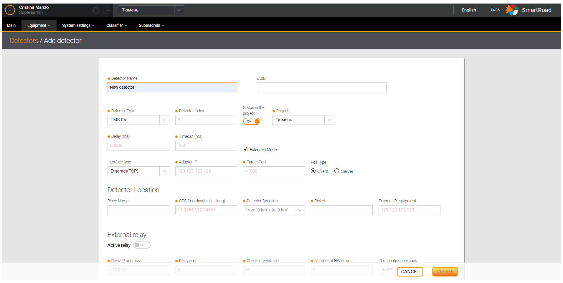
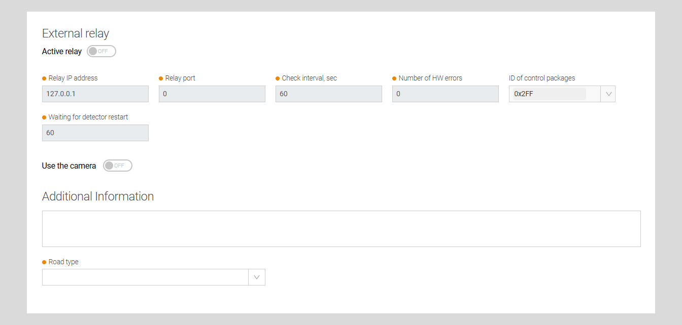
In the table are described the parameters in Add detector page
| Field name | Field description |
|---|---|
| Detector name* | The unique name of the detector is entered in the field |
| Detector type* | Select the series of the custom detector from the drop-down list |
| Detector index* | The detector index is entered in the field, which is assigned depending on the number of detectors in a given project (PUIDD 1, Adaptive intersection 4) |
| Project status | The switch that is responsible for turning on detector to the list of those polled by the adapter when connecting to adapter via DB or RabbitMQ. If you configure the adapter through a config file to display the detector in the web interface the commands sources must be specified. Otherwise the detector wont be displayed on the map |
| Organization* | The organization to which the detector belongs in the System. It is displayed if more than one Organization is registered on the System |
| Project* | The drop-down list indicates the project in which the detector will be included |
| Data latency *, ms | The delay time for receiving data from the detector is entered in the field. By default it is recommended to specify value = 60000 |
| Waiting for connection*, ms | The wait time for detector connection is entered in the field. By default, it is recommended to specify value = 100 |
| Advanced Mode | Checkbox for enabling advanced mode to the detector. This mode should only be enabled for detectors with series TMS.0C |
| Interface type | In the field, select the type of connection to the detector |
Depending on the type of DT created, the set of fields for filling out will change
Interface type Ethernet (TCP), Ethernet (UDP)
| Field name | Field description |
|---|---|
| Adapter/Detector IP address* | The IP address of the adapter or the IP address of the detector is entered in the field, depending on the survey type: - If Client is selected in the Poll Type field, the IP address of the computer on which the adapter is deployed, it will be indicated. - If Server is selected in the Poll Type field, the IP address of the detector is shown |
| Adapter/Detector port* | The adapter port or detector port to which the detector sends information depending on the polling type |
| Survey type * | It is used for selecting the operating mode of the equipment: Client Server |
Type interface Ethernet (TCP), Ethernet (UDP) for TMS.13
| Field type | Field description |
|---|---|
| Detector IP address * | Detector IP address depending on the survey type. |
| Data port | Port through which objects and PVR are transmitted |
| Port for commands * | The port through which commands are sent to the detector and responses to these commands are received |
| Survey type * | In the field the operating mode of the equipment: Client (inactive) Server |
Interface type RS-485
| Field name | Field description |
|---|---|
| Port name * | Port number, for example COM1 |
| Transmission speed * | Specify the transfer rate in bits/sec |
| Number of bits * | Standard RS connection setup |
| Number of stop bits * | Standard RS connection setup |
Ethernet interface type (Multicast)
| Field name | Field description |
|---|---|
| Adapter IP address | Enter the IP address of the adapter in the field |
| Detector IP address | The IP address of the detector is entered in the field |
| Detector port | The port used to communicate with the detector |
| Multicast group IP address* | Enter the IP address of the multicast group in the field |
| Multicast group port* | Enter the port of the multicast group in the field |
| Survey type | In the field the operating mode of the equipment: Customer (inactive) Server |
Detector location
| Field name | Field description |
|---|---|
| Place name | Enter the name of the location in the field detector installation |
| GPS coordinates (lat, long) * | The field indicates the GPS coordinates of the detector installation location. When creating a detector on the interactive map, this field is filled in automatically. |
| Detector direction * | In the drop-down list select the viewing direction of the detector related to the beginning location (0 kilometer) of the highways on which the current detector is installed. |
| Picket * | The name of the detector picket is entered in the field in the format km + m. Meters are entered from 0 when the value is less than 100 |
| External IP equipment | The name of the router's IP address or the PUIDD's IP address |
External relay
| Field name | Field description |
|---|---|
The Active Relay switch | Enables and disables the monitoring function for receiving data from the detector and restarting it when the configuration parameters are set |
| Relay IP address* | The network IP address of the module is entered in the field |
| Relay port* | The number of the interaction port with the detector is entered in the field |
Check interval *, sec | The value (in seconds) of the interval for checking the detector status |
| Number of HW errors * | The number of allowed hardware errors |
| Control Packet IDs | In the drop-down list, select one or more values of the control package identifier, which depend on the hardware model |
| Waiting for detector to reboot* | The waiting time for a reboot is entered in the field from 60 to 120 seconds, during which the detector is not monitored |
| Use the camera | The switch indicates that the camera is being used. If the switch is in the OFF state, The camera settings are not displayed. |
Camera Parameters
| Field name | Field description |
|---|---|
| Camera's IP address | The IP address of the camera is entered in the field. The default IP address is 127.0.0.1 |
| Port | The connection port to the camera. A number from 0 to 60000. The default value is 1111 |
| ID camera | The camera ID issued by the requester. The default value is 1 |
| Source | The data source for the camera. Possible values: - Server - Flow Default value – Server |
| RTSP-URL video stream | In the field is entered RTSP-URL the camera's video stream. Default value - rtsp://127.0.0.1 |
| Link to the photo request from the video server | A field for entering a link to request a photo from the video server. Default value - /jpeg? |
| Photo type | Camera photo format selection field. Possible values: - НЕТ - JPEG (default value) - PNG - GIF |
| Link to the video request from the video server | A field for entering a link to a video request from the video server. Default value - /video? |
| Video type | The video format is selected in the drop-down list: - none - avi - mkv - mpeg - mp4 |
| Manufacturer | The camera manufacturer is selected in the drop-down list: - Hikvision (default value) - Bosch |
| Camera login | Enter the camera's username in the field. Default value – admin |
| Camera password | Enter the camera password in the field. Default value – admin. |
| Preset number | The camera preset number is selected in the drop-down list. Numeric value from 1 to 10 (10 – Default value). The preset number is located in the camera's web interface |
| Directory to save photos/videos | Choosing the directory to save photos/videos from the camera. Default value - /home. |
| Additional information | A description of the detector and additional information about the detector are entered in the field |
| Type of road * | The road type is selected from the directory of road types in the drop-down list |
| Create | A detector with user-entered parameters is added to the System |
| Cancel | Undo all changes |
(*) - It means that the field is mandatory
You can determine the location of the zero (0) kilometer of the road on which the custom detector is installed on the website of the Road Funds Control System of the Federal Autonomous Institution ROSDORNII by using the following links:
When installing a detector at an intersection (as part of the PUSO), the specified intersection is taken as zero.
Here the Control packet ID values to be sent to the relay
| Control Packet IDs | Description |
|---|---|
| 0X320 | Loader mode (for all detector models) |
| 0X400 | Diagnostic message about detector setup (for UMRR-0C model) |
| 0X500 | Detector control message (for all detector models) |
| 0X501 | Message about the number of objects being transmitted and the number of messages for each object (for all detector models) |
| 0X502 | Message with the length of the object according to the class (for the UMRR-0C model) |
| 0X700 | Message about detector parameters (for the UMR-0C model) |
| 0X734 | Coprocessor status message (for the UMRR-0C model) |
| 0X780 | Statistical data message (for all detector models) |
| 0X785 | PVR message from the detector (for all detector models) |
This list is not exhaustive and is determined by the hardware integration parameters
Required fields whose values are entered incorrectly will be highlighted in red. The values in them must be changed.
In this case, the Create button will be inactive.
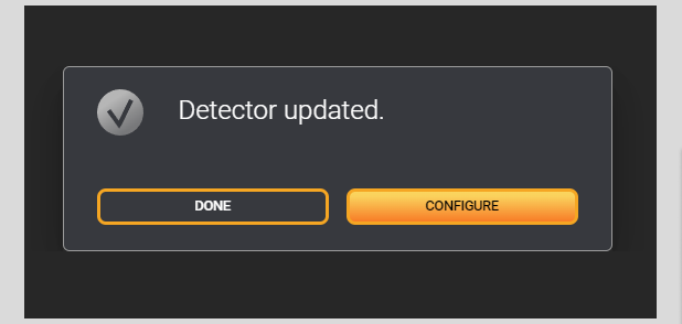
After entering the parameters and clicking the Create button, the system will prompt the user to save the entered data
without entering additional configuration parameters (then, click the Finish button) or enter additional detector configuration
parameters (click the Configuration button to do this).
Editing detector information
The page for Editing Detectors includes sections: Detector Configuration, Calibration. This functionality is configured
by technical support specialist of Sorb Engineering LLC.
You should move the mouse cursor over the line in the list with the selected detector or click on the edit button to change the detector parameters. When you click on the specified button, the detector editing page will open.
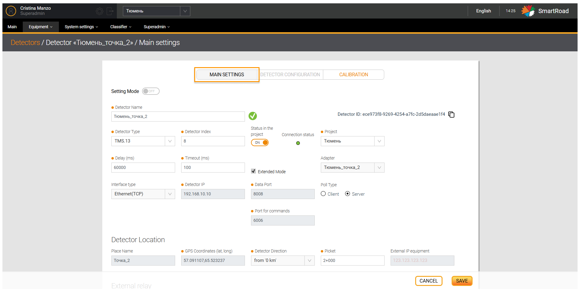
All section parameters in Main settings section are the same parameters that apply when adding a detector.
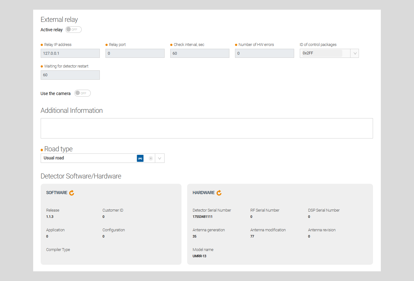
Additionally, information from the detector is displayed in subsections: Detector software/hardware - this information
is transmitted from the detector, and sections Detector zones, Detector lanes, Installation Parameters — are filled
automatically when the adapter is started. The data of the sections listed above can be updated by clicking on
the Update icon.
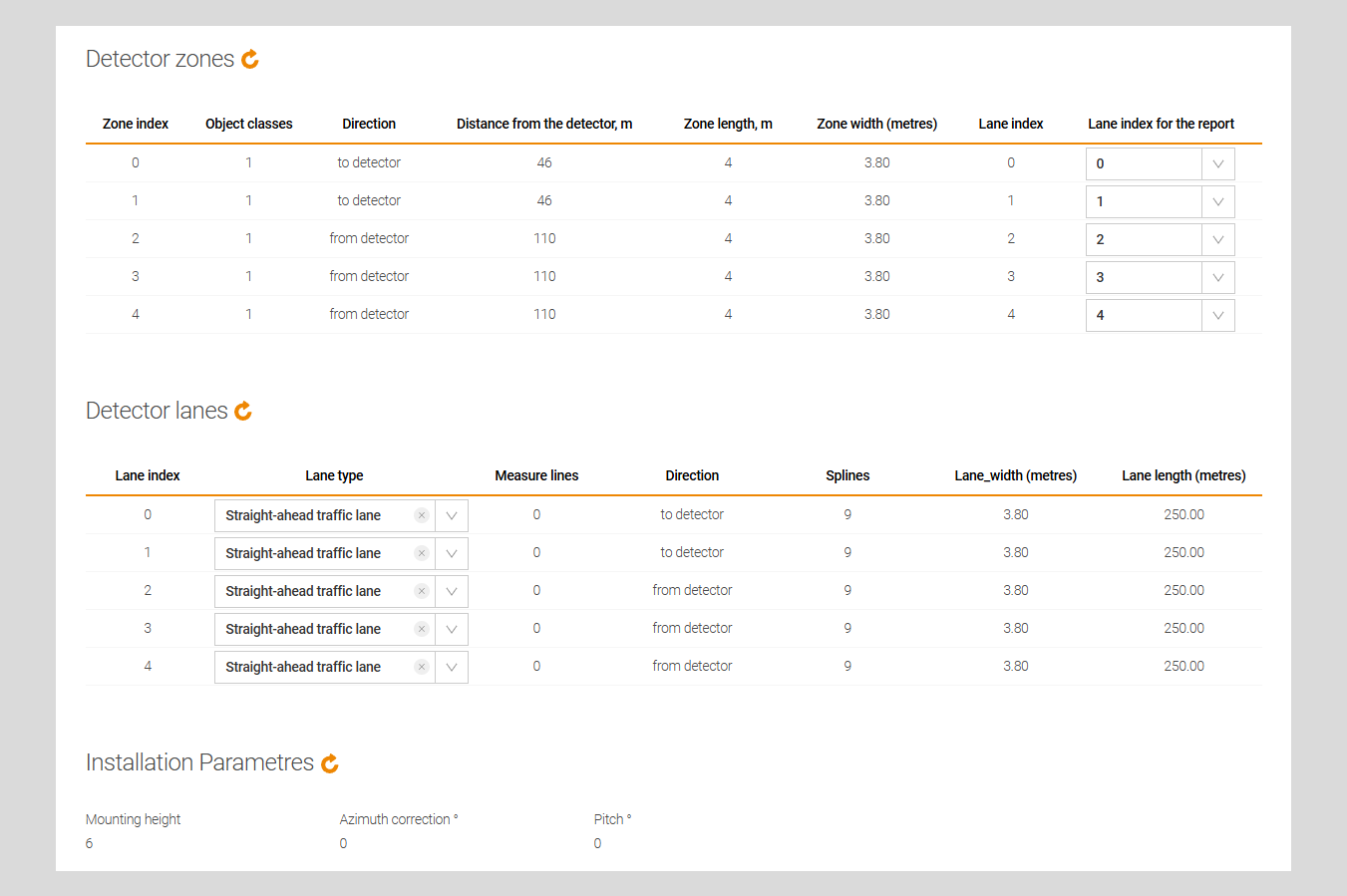
In the table you can find the Detector Zones parameters
| Field name | Field description |
|---|---|
| Zone index | Indexes of the zones associated with this detector |
| Vehicle classes | Number of vehicle classes |
| Direction | Direction of movement of detection zones |
| Distance from detector, m | Distance from DT in meters |
| Zone length, m | Length of the DT zone in meters |
| Zone width, m | DT zone width in meters |
| Lane index | Band index |
| Lane index for report | The index of the band that will be displayed in reports. Setting this parameter is used only if no bands are received from DT |
Besides the Detector Lanes parameters
| Field name | Field description |
|---|---|
| Lane index | Indexes of bands associated with this detector |
| Lane type | The type of lane from the road editor |
| Counting lines | Number of counting lines |
| Direction | The direction of the detector bands |
| Splines | Number of points for bending the road |
Lane width, m | Detector lane width in meters |
Lane length, m | Detector lane length in meters |
Here the Installation Parameters options
| Field name | Field description |
|---|---|
| Mounting height | Detector installation height |
| Azimuth correction | Azimuth angle of the detector |
| Zenith | Zenith angle of the detector installation |
You should turn on o switch Setting Mode to edit in tab Detector Configuration.
In addition, you must press the button Save to save the changed detector settings, and the button Cancel to dismiss.
Configuration
In this section, the detector configuration can be set. This configuration covers the following:
Algorithm for removing duplicate objects which may be used for removing duplicate objects (this option is only available to System technical support specialists) - the algorithm for removing counted vehicles i.e counted twice by the System due to detectors peculiarities or even conditions on the road.
Additional DT configuration options - detector network parameters, tracking parameters, detection parameters, primary data analysis.
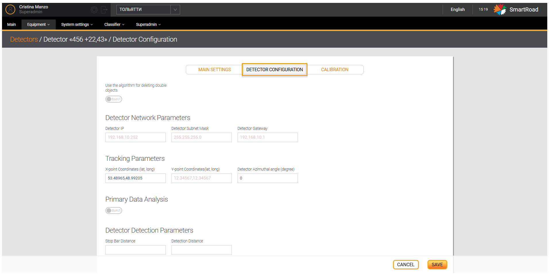
Additional detector configuration options
In this section you will find the Additional detector configuration parameters.
Detector network parameters
| Parameter type | Description |
|---|---|
| Detector IP address | Detector IP address |
| Mask reminded the detector | Mask reminded the detector |
| Detector gateway | Detector gateway |
Tracking options
| Parameter type | Description |
|---|---|
| X-point coordinates (lat, long) * | The field indicates the X coordinate of a point located at a distance of about 50 meters in the direction of viewing of the detector |
| Y-point coordinates (lat, long) * | The field indicates the Y coordinate of a point located at a distance of about 50 meters perpendicular to the viewing direction of the detector |
| Detector rotation angle (degrees) | The set angle of rotation of the detector relative to the road is entered in the field. |
| Previous detector* | In the drop-down list, select the name of the previous network detector |
| Distance to previous, m * | Distance between detectors from current to previous |
| Next detector * | In the drop-down list, select the name of the next detector |
| Primary data analysis | Switch that activates primary analysis of data from the detector |
Detection parameters
| Parameter type | Description |
|---|---|
| Distance to stop line | Enter the distance to the vehicle stop line in the field |
| Detection distance | The distance at which the detector will perform the initial registration of objects |
| Save | Saving detector settings |
| Cancel | Undo all changes |
(*) - It is a required field
Calibration
This page will display a list of all DT calibrations loaded into the System. You must click the button Add calibration to add a calibration to the System.
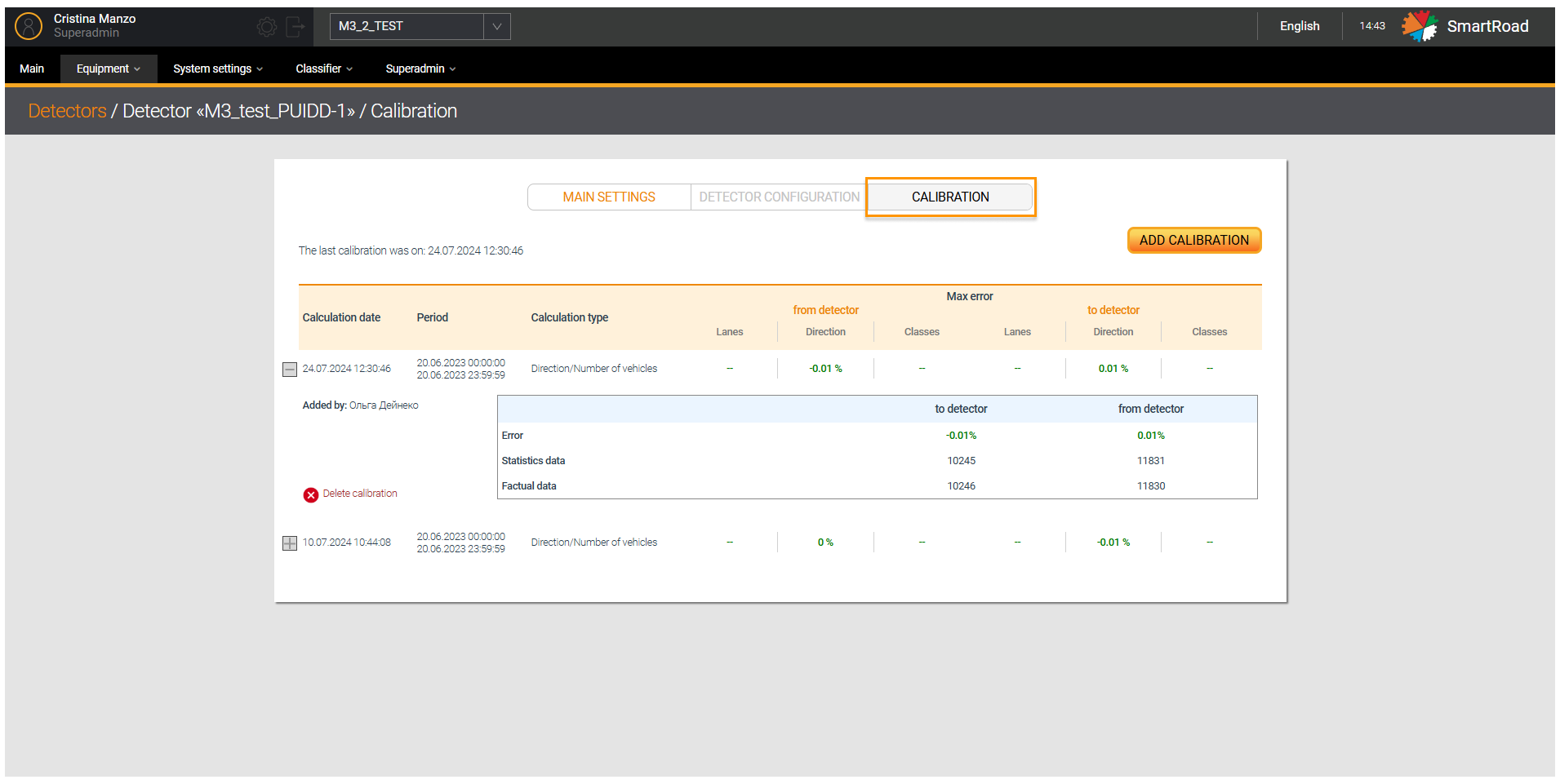
Adding a Calibration
In the Detectors page you should select the specific device. Next click on tab Calibration, and then on button Add Calibration
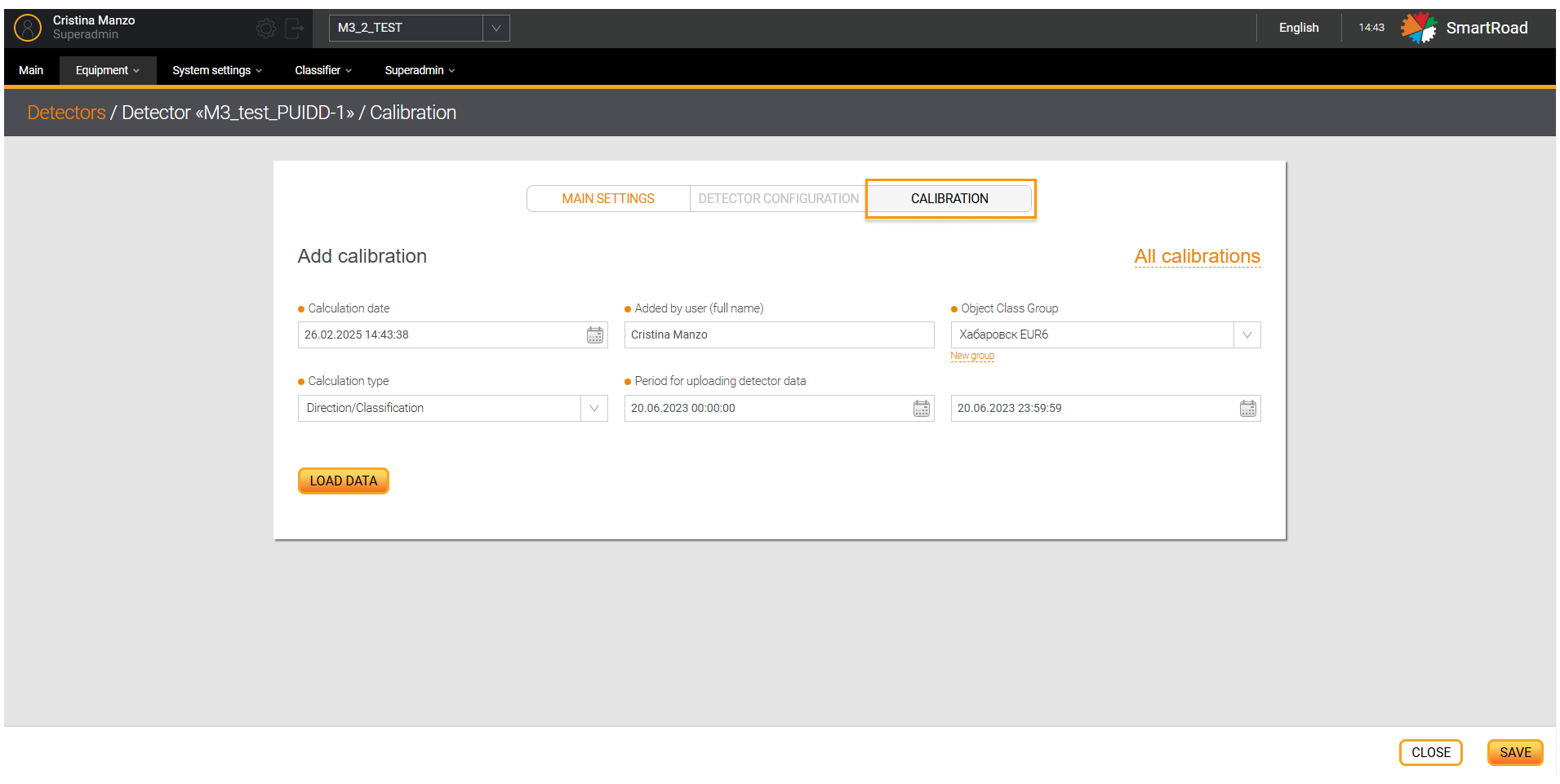
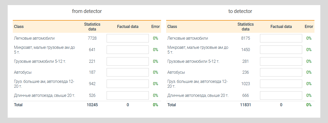
In the table below Add Calibration page options are described
| Field name/Buttons | Field description |
|---|---|
| Count date | The calibration date is selected in the calendar. This field is required. The default is the current date |
| Added by user Full name | This field indicates the user full name who configured the equipment. This field is required |
| Vehicle class group* | A group of vehicle classes combined into a group. This field appears only when you select the counting type by Direction and classification |
| Counting type | The system for calibration comparison is selected from the drop-down list. In this list, the user can select data for comparison with the System data - depending on the choice of calculation type, the table for entering diesel fuel calibration data will change. |
| Period for downloading detector data | The time interval is entered in the field, during which the error of the equipment is calculated. |
In addition the Table for determining measurement error. Here the direction of the DT is indicated
| Error type | Description |
|---|---|
| Counting type/Class | According to the selected calibration type |
| Statistics data | Statistics data obtained from DT |
| Actual data | Actual data counted by counters |
| Error rate | Change error |
(*) - Field is required
Fields whose values are entered incorrectly will be highlighted in red. Their values must be changed in the adding calibration section.
Removing a Calibration
Click on the Delete button to remove a calibration from the System, and confirm deletion in the dialog box.
Removing a detector
Click on the Delete icon to remove a detector from the System. When you click on this button, you must confirm the
deletion of the detector in a pop-up window by clicking the button or cancel the deleting action by pressing
the button Cancel.